Double block & bleed: understanding a barrier, part one.
Double block & bleed: understanding a barrier, part one.
There are a lot of misunderstandings with regards to the meaning of the phrases double block & bleed, double isolation, double active seal or double barrier. Double block and bleed in accordance to API means that there is pressure on both sides of the valve but nothing in the cavity. This is a good way of testing the seats integrity as up stream seat. But when it comeback to using the valve in connection with planed work on the down stream side of the valve the double block & bleed as in the API interpretation of the phrase has to be changed with something else; like double isolation or double barrier.
What do we mean when we state that we need double block and bleed? There is a lot of valve maintenance not carried out because it is not in accordance with double block & bleed. Let us go back and look at the valves in a production system, and then ask yourself, how many barriers are there between us and the hydrocarbon inside the piping system? The answer is, only one; wherever you go in the system there is never more then one barrier. It can be the wall of the pipe, a blind-flange, a blind plug or the spindle seal on a valve. There will never be more then one barrier in a running system. Looking at figure 1 you can see that the blue pressure is acting on the wall, pipe, bonnet bleed-plugs and the blind flange on the right side of the valve.
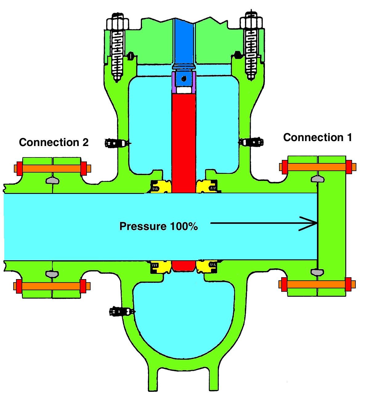
Figure 1.
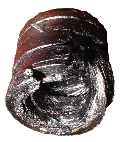
Figure 2.
Let me ask you another question; what is the most dangerous operation done on
a hydrocarbon system? The answer is:The daily operation of a high-pressure gate or a globe valve in a pressurized situation.The reason for this is that you start with a static seal (the stem seal) under pressure and rotate and raise the spindle, transforming the static seal to a dynamic seal. As long as the spindle moves on the inside of the seal there is a risk of creating an external leak past the stem packing, like the one illustrated in Figure 2.This graphite packing was on a 2” globe valve and blew out 240-bar gas when operated towards the open position. The danger of creating a leak is always greater when opening the valve because the stem is dragged outwards when the system-pressure is trying to force the packing material out of the box. Normally you don ́t even think about this because you have to operate the valves and you are used to doing so. I am not trying to say that one should not operate pressurized valves, but I am trying to focus on the way things are and the way things actually work. Remember; nothing is stronger than the weakest link.
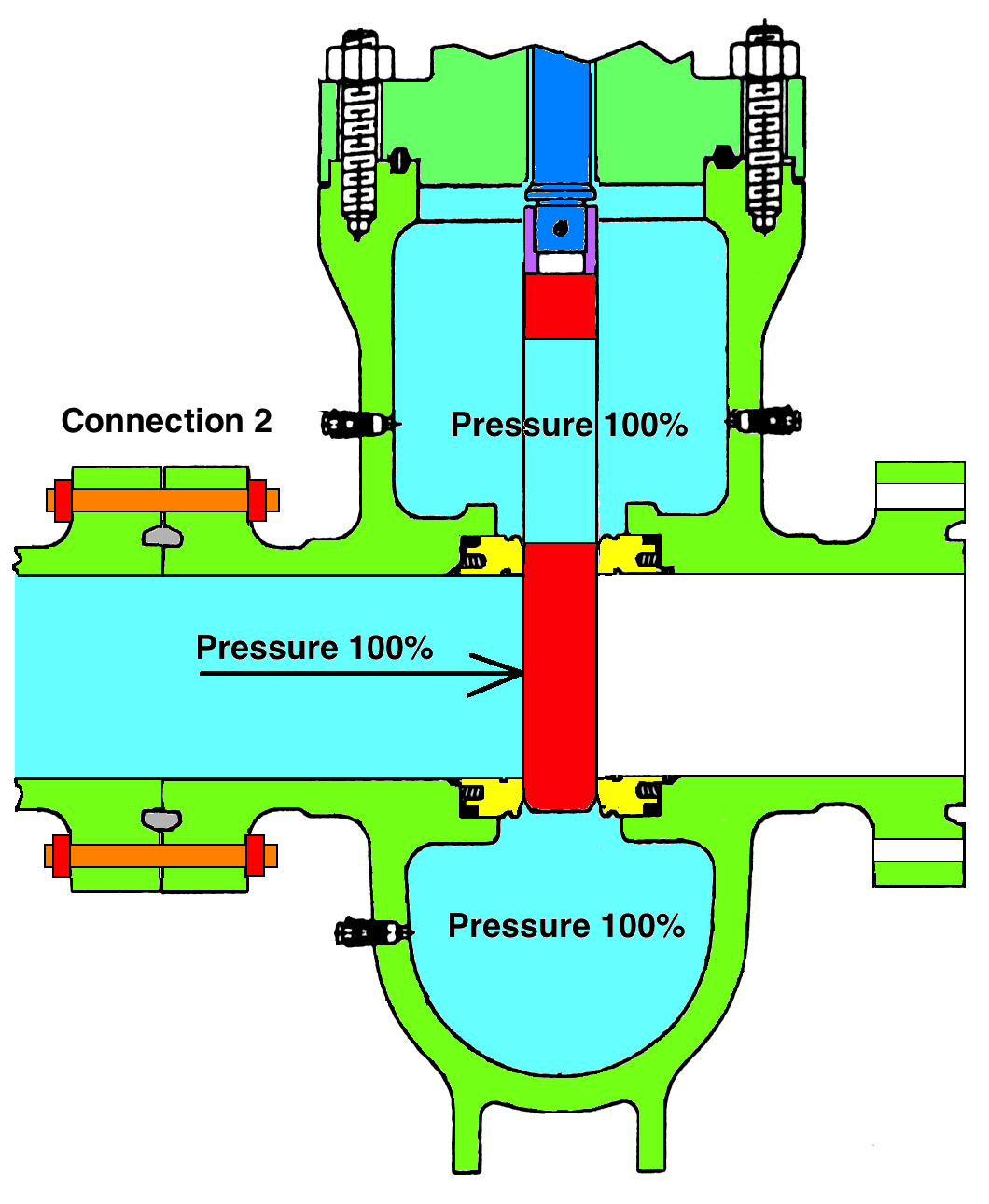
Figure 3.
Now let’s go back to Figure 1 and imagine that it is an 8” class 600 system with a system pressure of 100 Bar (1440 PSI). The illustration in Figure 1 could just as well be a straight pipe without a valve. The valve is in the open position and the pressure acts on the blind flange area which is about 320 cm2, with 100 bar system pressure, giving a total force of 32 000 kp (32 tons) acting against the blind flange.
Now it ́s time for a new question: Whatis creating the seal on the blind-flange in connection 1? The answer is the bolts connecting the blind-flange to the valve. If the pressure inside the flange increases, the seal force of the flange will decrease and you may risk a leak. This is a totally accepted situation and there is nothing wrong with that. But what happens if we close the valve, relieve the pressure on the down-stream side of the valve and disconnect the blind flange as illustrated in Figure 3? In this situation it is the gate in the gate valve holding the pressure towards the down-stream seat that creates the seal, but the high-pressure acting on the gate will provide a much safer seal than one on the flange. The force acting on the bolts of connection 1 in Figure 1 will, in Figure 3, be acting on the bolts of connection 2. In reality there is not much difference between the situations in Figure 1 and Figure 3 except that the actual seal-force is better in Figure 3.As long as the valve has a tight seal when closed it can never start to leak if not operated towards its open position. Yet the situation illustrated in Figure 3 will not be accepted due to the lack of double block and bleed.
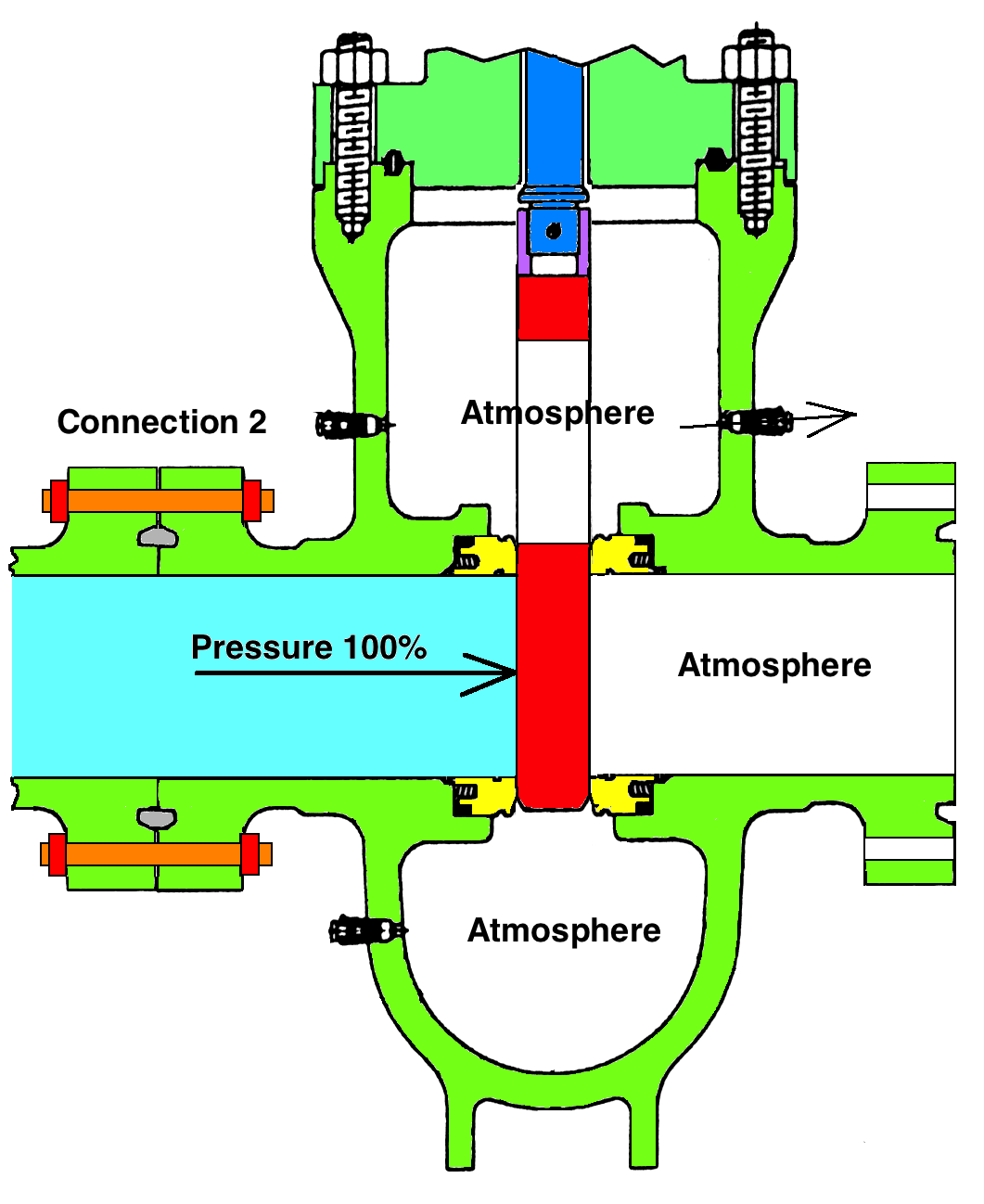
Figure 4.
Let ́s go a step further and release the pressure from the cavity of the valve, as shown in Figure 4.The differences now are that the valve itself has two seals in the pressure direction.The first seat seals against the gate, there is no pressure in the cavity and the gate seals against the second seat.We have a valve with two activated seats in the pressure direction! But we still have the same situation with regards to the upstream flange connection 2.The nuts in that connection will hold all the forces acting on the gate.
All plants and installations will accept a situation as shown in Figure 1. No plants or installations will accept the situation as illustrated in Figure 3, but some plants and installations will accept the situation illustrated in Figure 4. Personally I would have no trouble working at the back of a valve like the one illustrated in Figure 3. It is a perfectly safe situation when there is a high-pressure seal in a gate valve but it is much more unstable with a 5 bar low-pressure seal. I have never been in, or heard of, a situation where a parallel gate valve with a high differential pressure seal suddenly started to leak.
To be continued…
Vil du laste ned denne artikkelen som PDF?
Klikk her for å laste ned