
In the last three articles we have been looking at different ways for valves to seal, different valve constructions like double expanding gate, solid slab gate, trunnion mounted ball valves with self-relief seats, double piston seats or the combination DPE / SPE construction.
I would like to go back to the beginning of the first article (Valve World December 2014) to the question: What do we understand by the phrase double block and bleed, double isolation or double barrier in one valve?
What most production personnel would do to get a double isolation / double barrier in one valve is to close the valve and relieve the pressure from the cavity. The problem now is that it all depends on which valve we are dealing with. Is it a gate valve or a ball valve and is the ball floating or trunnion mounted? What type of seat arrangement and seals is the valve equipped with? Before doing a job on a valve you need to know how the valve works, what is safe to do and what is unsafe to do.
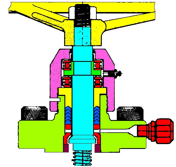
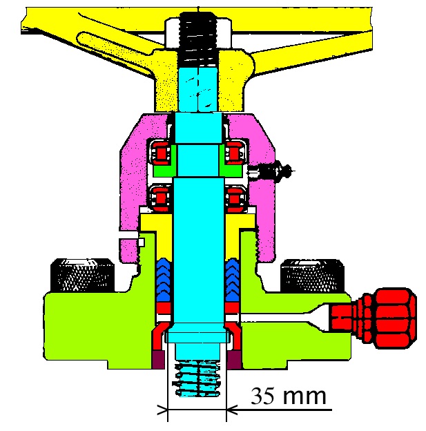
Once I was in a situation where there was a spindle leakage on a manual master valve on the wellhead, the valve was equipped with a stationary spindle, see Figure 18, that was leaking quite a lot. There was around 250 bar production-pressure (three phase). I placed the valve in the back seat position by turning the bearing cap 3 turns out, as illustrated in Figure 19. The valve was still in the open position under full production, but the spindle leak stopped, which indicated a spindle and bonnet seat in good condition.
Now the discussion starts. We had to change the spindle seals and the safe way of doing that (in accordance with the procedure) was to shut down, set a plug and change the stem packings. But is this the safest way? To set a plug to create double block & bleed upstream of the wellhead you have to connect the lubricator with the BOP to the swab valve and set a plug by means of wire line. You have to go through the wellhead to set the plug above the down hole safety valve then retract the wire and reduce the pressure between the plug and the wellhead. And finally you can change the packings after spending more than one million US $. Now you have to go down and pick up the plug before production can start up again. If you are lucky the operation only takes a day and the fact is that this is one of the most dangerous jobs to be done on a platform!
My argument in this case was to keep the valve in the back seat position; one could stop production but there was no need to do so, use a stinger on the lubricant fitting to test the back seat. In fact I knew it was OK as there was no leakage out of the stem. Looking at Figure 19 you can see that the spindle area exposed to the pressure has a diameter of 35 mm which gives an area of 9.6 cm2. With a production pressure around 250 bars the force from the system-pressure holding the spindle seat in contact with the bonnet seat equals a force of 2.4 tons. You can ask the questions; why are gate valves equipped with spindle seat and bonnet seat? And why is the spindle seal/bonnet seal tested on new valves as part of the FAT? The safest way of replacing leaky spindle seals is actually with the valve in the back seat position. The major problem was the lack of double block & bleed, there was only one seal (back seat) holding the pressure. If one thinks of it, when operating the same valve in a normal situation, how many seals do you have between the pressure and the atmosphere? As we all know, we have only one and that is dynamic when operating the valve.
I was asked to write a procedure, what to do and how to do the job step by step, which I did, and was given acceptance to do the job with the valve fully pressurized. The production was stopped “just to be on the safe side” and the down hole safety valve on that well was closed.
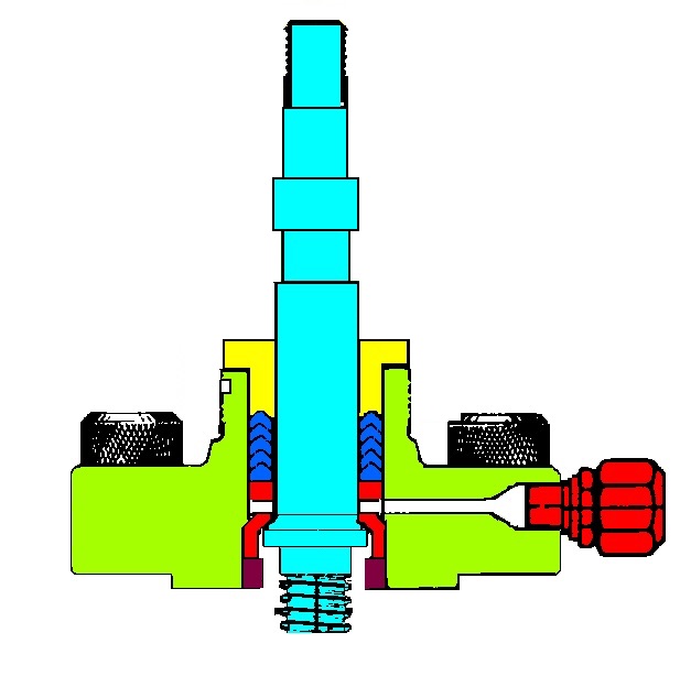
After dismantling the wheel, the bearing cap and the bearings the valve looked like Figure 20. As you can see the spindle seal was still not touched, there was no leakage out of the stinger that was connected to the fitting. We loosened the packing retainer at which point there was some nervousness among some of the personnel, but remember there was a force from the system pressure equal to 2.4 tons holding the spindle in the back seat position.
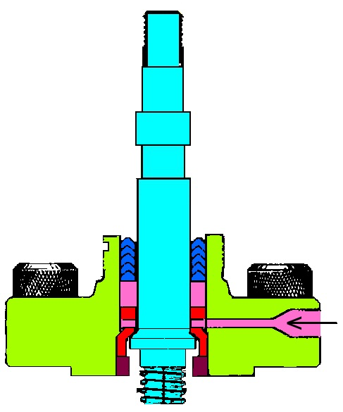
After dismantling the packing retainer we pumped in grease through the stinger/ fitting, illustrated in Figure 21, and the grease squeezed the packings out. This raised a question; what if the packings were stuck and the injected grease forced the spindle downwards creating an opening between the spindle and bonnet seat? This is not possible as the system pressure forces on 9.6 cm2 the injected grease will act only on 1.5 cm2 (the area on the outside of the spindle). You would need 6.4 times the system pressure (1 600 bar) to do so. The injected grease will act under the spindle packings on an area of 21 cm2 forcing the packings out. This was perfectly safe.
After taking off the old packings, cleaning most of the grease out and disconnecting the grease gun the packing seal area on the spindle was inspected and the new set of packings was installed. The packing retainer was reinstalled and tightened to the correct torque. The rest of the parts were installed and the bearing cap was tightened taking the spindle out of the back-seat position. There was no spindle leakage after finishing the job.
Although this was a safe job to do, you need to know what to do and how to do the job safely. If untrained personnel start doing these kind of jobs you can end up with a disaster. To be able to safely do valve maintenance jobs you have to train your personnel!
To be continued…