
The injection of lubricants
After installing the leak lock on to your fitting, it´s time to inject cleaner, lubricant or sealing component. To be able to inject anything into the valve you need a pump. It may be a pneumatic or a manual pump, it does not matter what type of pump you are going to use, what does matter is that the pump do have a pressure gauge to indicate the injection pressure. When injecting in to a fitting, and especially if you are injecting into a pressurized system you MUST know the injection pressure.
Figure 55
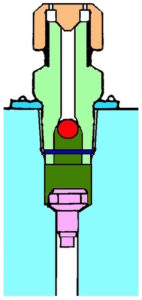
Without you knowing the injection pressure there may be a blocking in or between the fittings. If looking at figure 55, witch shows; the pink inner check, the light green fitting with the orange cap on. In between the pink inner check and the green lubrication fitting there is a volume marked dark green. Lets say that volume contains hardened something; witch is blocking the possibilities to inject anything into the valve. If that fitting was installed as a lubrication fitting to the inlet seat of a trunnion mounted ball valve, the volume below the inner check valve will go directly to the inlet piping of the valve.
Let`s take a scenario from a gas plant where a mechanic should perform maintenance on a 24” class 600 trunnion mounted ball valve. First of all he did not use leak lock, but that would not have made any change in the situation anyway. The mechanic was using a manual pump without a functioning gauge on the pump. He was able to inject a small amount, but then it stopped and he could not inject any more. Without knowing the pressure of the pump he increased the pressure trying to open the blockage in the fitting. The situation got suddenly dramatic as the lubrication fitting flew of the valve and gas was blowing out of the hole where the fitting once was installed. Nobody got hurt, but the plant did shut down due to the gas leak (between 50 and 60 bar).
The threads of the fitting were not able to hold the fitting in place, when over pressurizing trying to open the blockage. They later found out that the fitting probably was over tightened some time earlier, where they had a small leak out the NPT threads, and fixed it by tightening the fitting. I have stated many times that I don´t like NPT threads, you don´t always know the condition of the threads.
Anyway, this incident would not have happened if a full functioning gauge were installed on the pump. If having a class 600 valve with between 50 and 60 bar on inside the pressure injected should in any circumstances not exceed 150 bar witch is the hydrostatic test pressure of the valve (150%). The fitting is probably capable of 600 bar, but it is a class 600 valve and that’s where you have the limitation.
In a situation like this, its only one thing to do: When having a gauge on the pump, inject valve cleaner at the maximum allowed pressure and leave it, allowing the valve cleaner to dissolve the pug in between the inner check and the lubrication fitting. If the valve cleaner can´t dissolve the plug; you must wait for the system to be depressurized before dismantling the fitting, cleaning and installing a new lubrication fitting.
It´s not only dried products that can cause a blockage in the canals or in the inner check valve. There are several manufacturer and several qualities of the sealing component.
Figure 56 Figure 57
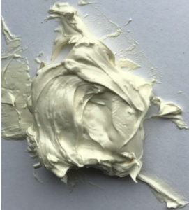
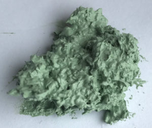
Figure 58
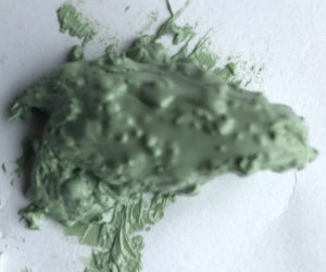
The sealing component in figure 56 is a component consisting of microscopic PTFE particles in a viscous lubricant. It is not possible to see the particles in the component. The sealing component in figure 56 can seal leakage from small to medium scratches up to 0.3 mm. The component in figure 57 consists of larger visible PTFE particles, and seals scratches, pitting up to 0.7 mm. In figure 58 the PTFE particles are equal in size compared to the particles in figure 57, but there are more of them, allowing sealing of leakage from some larger damages. This is only three examples of a large variety of sealing components on the marked. There is a variety in the viscosity and with regards to the quantity and dimension of the particles in the component.
When injecting heavy sealing component through the lubrication fittings and the inner check (witch normally have the smallest flow path) and into the valve, there may be a risk of blockage. If having a block due to the sealing component clogging of the inner check in the injection canal, you may end up in trouble if you are trying to solve the problem with excessive force (pump pressure).
There is a good role of thumb: Always use the lightest possible sealing component. It is better to have a small leak witch you can control, then to end up with a blockage in the fittings witch unable you to work with the valve.
As we have been discussing earlier, the lubrication fittings in a parallel gate valve are placed in the cavity side of the valve and in many cases will be without an inner check valve. On a plug valve the lubrication fitting/s will also be placed towards the cavity and if having trouble you could actually tighten the plug into the housing wall to reduce a leak passing the valve. But in a trunnion mounted ball valve there should always be a double check as the lubrication canal to the seats ends up on the inlet side of the seat and you will always have the pipe volume on the end of the canal. Because of this you should avoid using heavy sealing component (as the one in fig 58) in trunnion mounted ball valves. It won’t do you or your company any good having an accident when trying to maintain a valve.
To be continued…