
The lubrication fittings
In this series of articles, we have been discussing the need for lubrication fitting and why one should use valve cleaner and sealing component. We have also been looking at why one should have an auxiliary valve in the cavity of the main valve.
We all know that all connections on the valve body are possible leak points, and where one in the worse cases my suffer HC leakage. For those reason there are installations or plants where the major ball/ gate valves are installed with lubrication fittings in the body, BUT nobody are allowed to touch them as long as there are pressure in the pipe system. This because there my occur a leak in the fittings after the preformed maintenance.
Yes, that is true, if allowing personnel without the proper skill doing maintenance, you may end up with a leaky valve or an accident with personnel injury. But that is no reasons for not maintaining the valves. If you allow a person without driving licence and the proper training drive your car on the freeway in the rush hour, you ask for accident and it may be a fatal one as well.
As I have stated several times: Personnel performing maintenance on pressurised valves MUST use the correct safety equipment, and they MUST be trained in valve maintenance.
Now you could ask: What safety equipment do you need when performing maintenance on the valve? The most important safety equipment is the leak lock witch is to be installed on top of your lubrication fitting. I would never clean or lubricate a pressurised valve without a leak lock. The leak lock is the safety device that if the installed fitting starts to leak when working with the valve, you still could stop the HC from leaking out to the atmosphere.
Figure 51 Figure 52
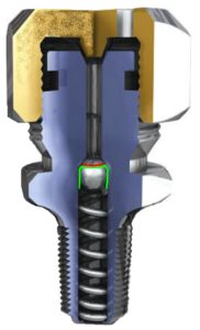
 You may ask why a safety device is needed. Looking at figure 51; Imagine the red line is a small damage to the ball due to vibration, as long as it is in the same position the ball seals. But what happens if something is injected past the ball and the ball rotated slightly? Then the damage would cross over the seal area and the ball would leak. If the ball sealed due to heavy hydrocarbons (green line) on the ball surface, and the valve + the ball in the fitting was cleaned, then the fitting could start to leak.
During the time I have done valve maintenance, I can´t count all the times I have ended up with a leaky fitting and then ended up using sealant component to seal of the fitting.
There are several types of lubrication fitting; threaded types with different dimensions and types on the treads, button head small and large and with or without a cap. We need leak locks for all the types of lubrication fittings.
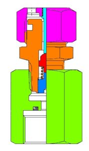
Figure 52 illustrates a leak lock to be used on fittings with treaded connection. It could be ½”, ¾”, 1” or 27 mm parallel treads. You can see that the leak lock consists of an adapter with a lubrication fitting on the top. But what is important with the leak lock is; after the maintenance you need to be able to test the inner lubrication fitting witch the leak lock that is installed on top of it.
If looking at the leak lock in figure 52, one can se that the cap consists of two parts; the cap itself (pink) and a needle in the centre (blue). After taken the button head connection from the pump away from the leak lock, one will test the inner fitting by taking the cap with the needle and screw it on to the top of the leak lock. Turn it down until the needle hits the check and pushes it away from the seat. If having a leak, the leak will flow out the holes of he cap and one will unscrew the cap with the needle. The inner fitting can be sealed by the use of a small amount of sealing component, or a standard cap can be installed on the leak lock and the leak lock will be left on the fitting until the fitting can be replaced.
Figure 53 Figure 54
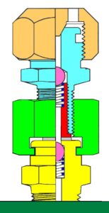
 The illustrations in figure 53 and 54 shows two different types of leak locks. In figure 53 the fitting installed in the main valve (yellow) is a button head type without a cap. I personally would recommend NOT using that type lubrication fitting on HC systems. But if it is installed, you need a leak lock with button head connection and soft seal towards the top of the fitting.
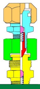
The lubrication fitting in figure 54 is a button head with cap. On this one you could also use the leak lock type illustrated in figure 52. But back to the leak lock in figure 54, which is metal-sealed towards the cone on top for the fitting.
When installing the leak locks illustrated in figure 53 and 54, you slide the leak lock on to the button head and tighten the leak lock by rotating the upper fitting (blue) and holding the adapter (green). You are now ready for injection through the leak lock and the lubrication fitting.
When the maintenance is done and you are ready for disconnection of the equipment. Disconnect the button head connector from the leak lock and hold the adapter (green) with a wrench and carefully unscrew the upper fitting (blue). If nothing comes out, the inner ball in the lover fitting seals and you can disconnect the leak lock. But if when unscrewing the upper fitting (blue) and a leak should occurs between the adapter (green) and the main fitting (yellow), you should re-tighten the leak lock and inject a small amount of sealing component, or install the cap on the leak lock and leave it on the fitting for to be replaced sometime when the system is depressurised.
Take care when injecting anything into a pressurised systems.
To be continued